
Setting up a cruise control stalk (Nissan Patrol)
A cruise-control stalk is usually a resistor ladder — each button switches a different resistance onto one signal wire, so the dash can tell them apart by voltage. The Expander reads it directly: the cruise channel has an on-board software-selectable pull-up, so the ladder just connects to the channel and you teach the buttons in the dash. No external resistor — the same on both the Standard and the Pro. First, work out which Patrol switch you have.
Nissan Patrol cruise switches — early vs late
Patrol ASCD (cruise) switches come in two styles, and they wire in differently. Check which you have before you start:
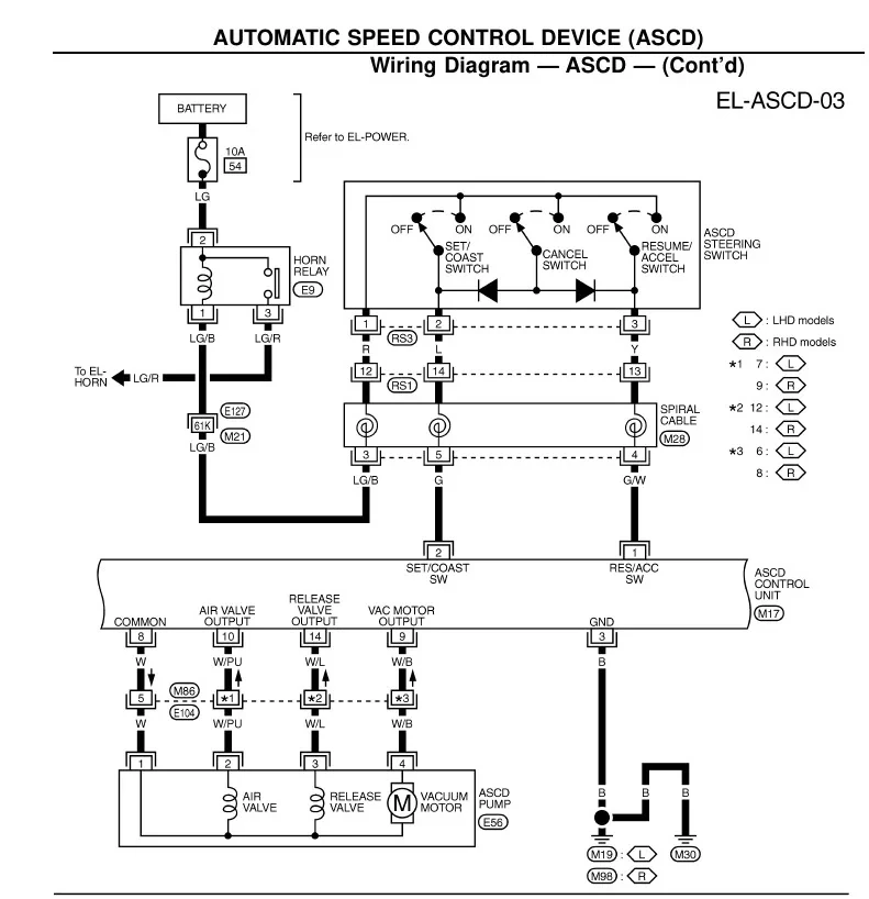
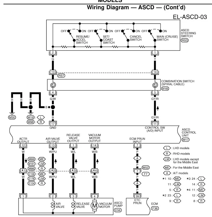
Diagrams: Nissan Patrol factory service manual (ASCD). Click either to enlarge.
Why it just works (late / A-D ladder)
A resistor ladder only changes resistance as buttons are pressed, so it needs a pull-up to a reference to turn each press into a distinct voltage. On the Expander that pull-up is built in on the cruise channel, so the ladder connects straight to the channel — nothing to add in the harness.
Wiring the ladder
Pick the channel
The cruise ladder uses the AN5 analog channel — find it on the analog connector by the board's silkscreen channel label.
Connect the ladder
Ladder signal wire → the channel's signal pin. Ladder common / return → the channel's ground pin. Two wires, no resistor.
Secure and protect
Crimp and heat-shrink, keep the run clear of injector and ignition wiring, and loom it in.
Set it up on the dash
With the ladder wired, finish in the Helm Commander configuration screens:
- Assign the channel to cruise control and turn on its pull-up.
- Teach each button — press one at a time so the dash records its voltage level and maps it to the action (set / resume / coast, etc.).
- If the button levels bunch up and can't be told apart, change the pull-up range and re-teach so they spread out.
- Run through the buttons and confirm each is recognised cleanly, with no overlap.
Troubleshooting
- No buttons register — the pull-up is off, or the ladder signal / ground is open. Enable the pull-up and check the two wires.
- Buttons run together — pull-up range doesn't suit this ladder; change the range and re-teach so the levels separate.
- Some buttons work, others dead — a break in the ladder itself or its return; meter the ladder button-by-button to ground.
- Levels drift or jump — poor ladder ground; return it to the channel ground, not a random chassis point.