
Wiring the brake inputs for E38 cruise control
On a GM Gen IV drive-by-wire engine, cruise control lives inside the E38 ECU — there is no separate cruise module. It will not set or hold a speed until it sees a valid brake signal it can trust to cancel on. Get the brake wiring right and cruise just works; get it wrong and you get "cruise unavailable", a set that instantly drops, or a brake-related DTC.
Why the E38 needs a brake signal at all
Because the E38 controls an electronic throttle, cruise control is a software function inside the ECU rather than a vacuum servo or a standalone box. For that software to be allowed to hold your throttle open, it must have a dependable way to know the instant you touch the brake — so it can drop cruise immediately.
GM treats that as a safety-critical input, so the ECU looks for the brake state on more than one signal and expects them to agree. If a brake signal is missing, stuck, or the two indications disagree, the ECU assumes it can no longer guarantee a clean cancel and simply refuses to offer cruise (often logging a brake-switch DTC). That is the single most common reason cruise "won't turn on" on an E38 swap — the engine runs fine, but the brake inputs were never wired in.
The signals the E38 is looking for
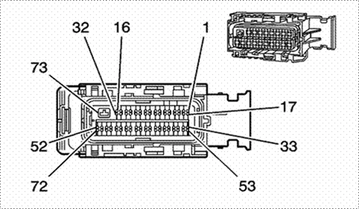
Cruise control on the E38 needs a dual-switching brake sensor — a single dual-pole switch at the pedal that drives two opposite-logic signals into the ECU's J1 connector:
- Brake applied — J1 pin 9. The ECU must see 12 V when the brake is pressed (and no voltage when it's released). This is the normally-open pole, the same "brake is on" indication that drives the stop lamps.
- Cruise enable — J1 pin 7. The exact opposite: 12 V at all times until the brake is pressed, at which point it drops out. This is the normally-closed pole.
The ECU watches both. Under normal driving pin 7 is high and pin 9 is low; the instant you brake, they swap. Because the two must always disagree in that way, a single stuck or broken contact can't leave cruise unable to cancel — that redundancy is exactly why the E38 insists on both before it will offer cruise.
E38 brake-input connections
| Signal | J1 pin | Brake released | Brake pressed | Notes |
|---|---|---|---|---|
| Brake applied (stop-lamp) | 9 | 0 V (open) | 12 V | Normally-open pole — closes to 12 V on brake press. |
| Cruise enable (redundant) | 7 | 12 V | 0 V (open) | Normally-closed pole — opposite logic to pin 9; 12 V until you brake. |
| Switch feed | — | +12 V | +12 V | Fused +12 V (switched / ignition) to the common of the dual-pole switch. |
What you'll need
- GM dual-pole brake pedal switch (or your vehicle's original switch, if retained)
- The correct E38 connector pinout for your vehicle (service manual or verified swap pinout)
- A digital multimeter
- Automotive wire to match the loom, crimp/solder terminals and heat-shrink
- An in-line fuse and holder for the switch feed
- Your Helm Commander — the Tuning page to apply the Brake input patch, and the Cruise page to check the inputs
- Recommended: the factory cruise stalk, or momentary buttons via the Expander module, for set / resume / coast on the move
Wiring it in
The wiring itself is only two signal wires and a feed — genuinely straightforward. Most of the time you'll spend is just getting to the ECU, so how long it takes comes down to where yours is mounted.
Confirm the J1 pins
Locate pin 9 (brake applied) and pin 7 (cruise enable) on the J1 connector and mark the cavities. Count carefully — the E38's connectors are each numbered on their own, so make sure you're on J1.
Wire the dual-pole switch
Feed the switch common from a fused +12 V source. Run the normally-open pole to J1 pin 9 (goes to 12 V on press) and the normally-closed pole to J1 pin 7 (12 V until press). Keep the stop-lamp side intact so your brake lights still work — the ECU shares that "brake applied" signal, it doesn't replace it.
Route, protect and secure
Run the signal wires away from ignition/injector wiring and sharp edges, use proper crimps or solder with heat-shrink, and fuse the feed. Loom and secure everything — a chafed brake-signal wire is a cruise fault waiting to happen.
Bench-check before power-up
With the battery still disconnected, use the multimeter on continuity to confirm each switch pole opens and closes correctly as the pedal moves, and that there are no shorts to ground or between the two signals. Only then reconnect the battery.
Apply the Brake input patch & verify
Wiring alone won't do it — the E38 has to be told to use those inputs, which means changing the ECU parameters. With Helm Commander both the change and the check happen right on the dash, no scan tool needed:
- Apply the Brake input patch — Tuning page. This writes the ECU parameter changes the E38 needs to act on the brake signals. Wire the pins perfectly and skip this, and cruise still won't work.
- Check the inputs — Cruise page. Work the pedal and watch the brake input state change live on the dash — a quick confirmation with no back-probing.
Beyond the brake inputs, cruise needs a valid vehicle-speed signal and a way to drive it. The Cruise page can switch cruise on right from the screen — but for set, resume and coast on the move we recommend wiring in physical controls: either the factory cruise stalk, or separate momentary buttons through the Expander module. With the patch applied and the inputs confirmed on the Cruise page, take the vehicle to a safe, open road, set cruise and confirm it holds — then tap the brake and confirm it cancels instantly.
Troubleshooting
- Cruise never becomes available — a brake signal is missing, or the Brake input patch hasn't been applied from the Tuning page. Confirm both inputs move with the pedal on the Cruise page, and that the patch is applied.
- Brake-switch DTC set — the two indications disagree. Usually a mis-pinned wire, a single-pole switch used where a dual-pole is required, or a broken contact.
- Cruise cancels randomly — intermittent signal: chafed wire, poor ground, or a marginal switch.
- Brake lights work but cruise won't cancel on the brake — the stop-lamp side is fine but the ECU brake pin isn't actually connected. Re-verify the pin at the ECU.